An engine to gearbox adapter: from 3D scan to print to aluminium (process study)
A process study built on an engine swap: a Toyota 2JZ with a 6-speed manual gearbox. The gearbox side comes straight from a 3D scan of a real case: the bellhousing flange plane, its 8 bolt holes and outline. Between the block and the bellhousing sits an adapter plate that has to match two different bolt patterns, two sets of dowels and the crankshaft axis. The rule is simple: before you pay for machining solid aluminium, you check everything on a cheap print. Scan, model, a plastic template, a trial fit, and only then CNC at a trusted partner.
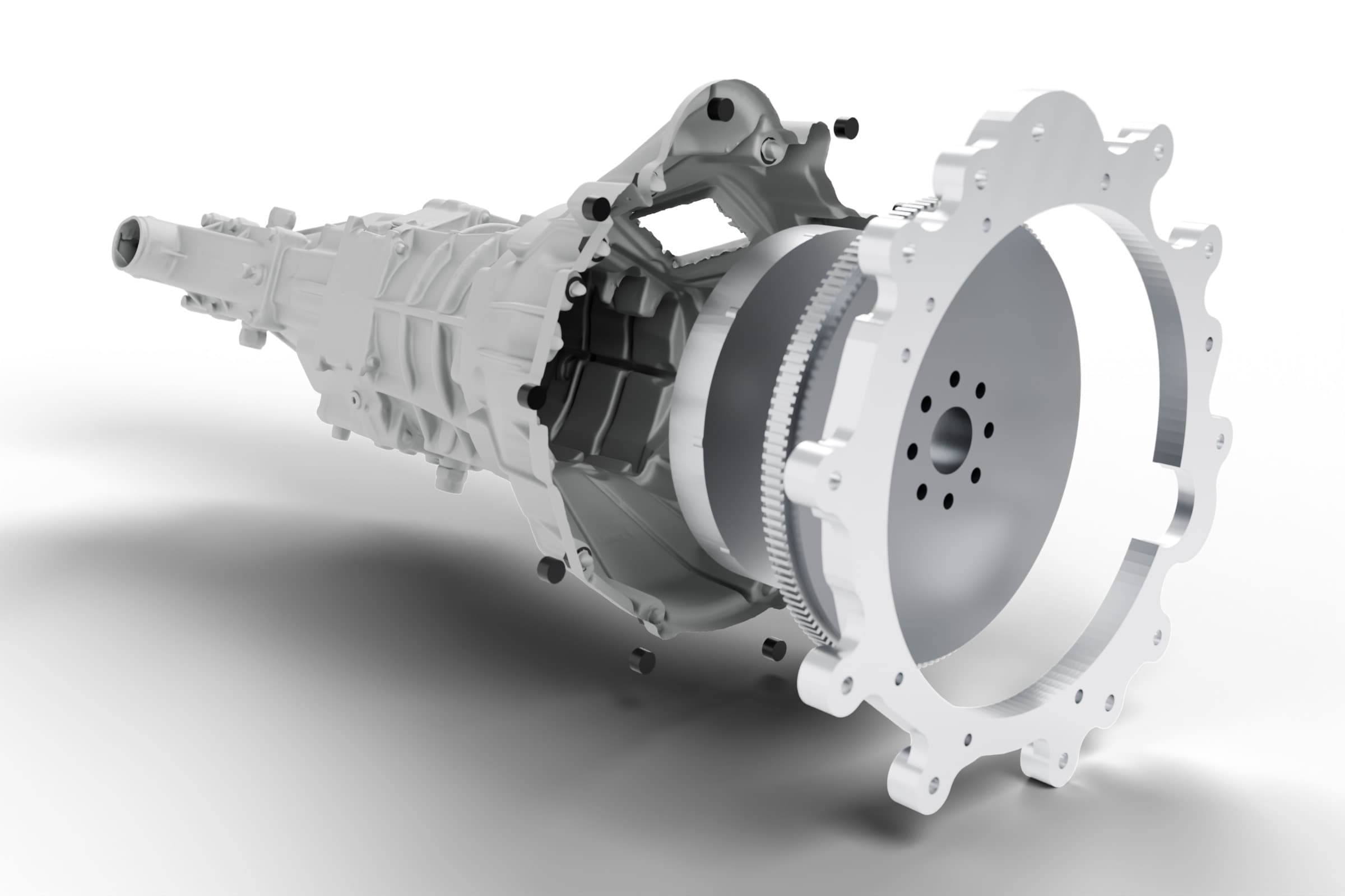
From scan to aluminium
04- 01
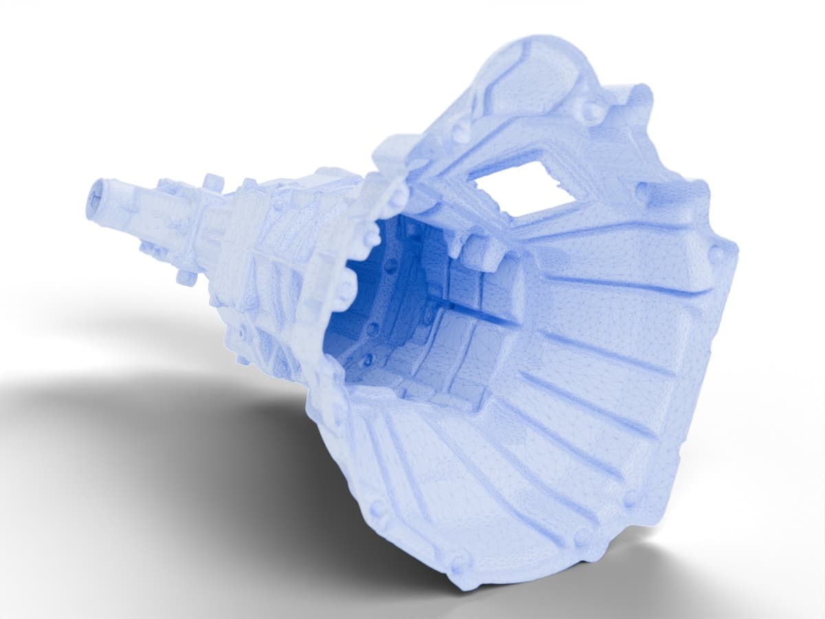
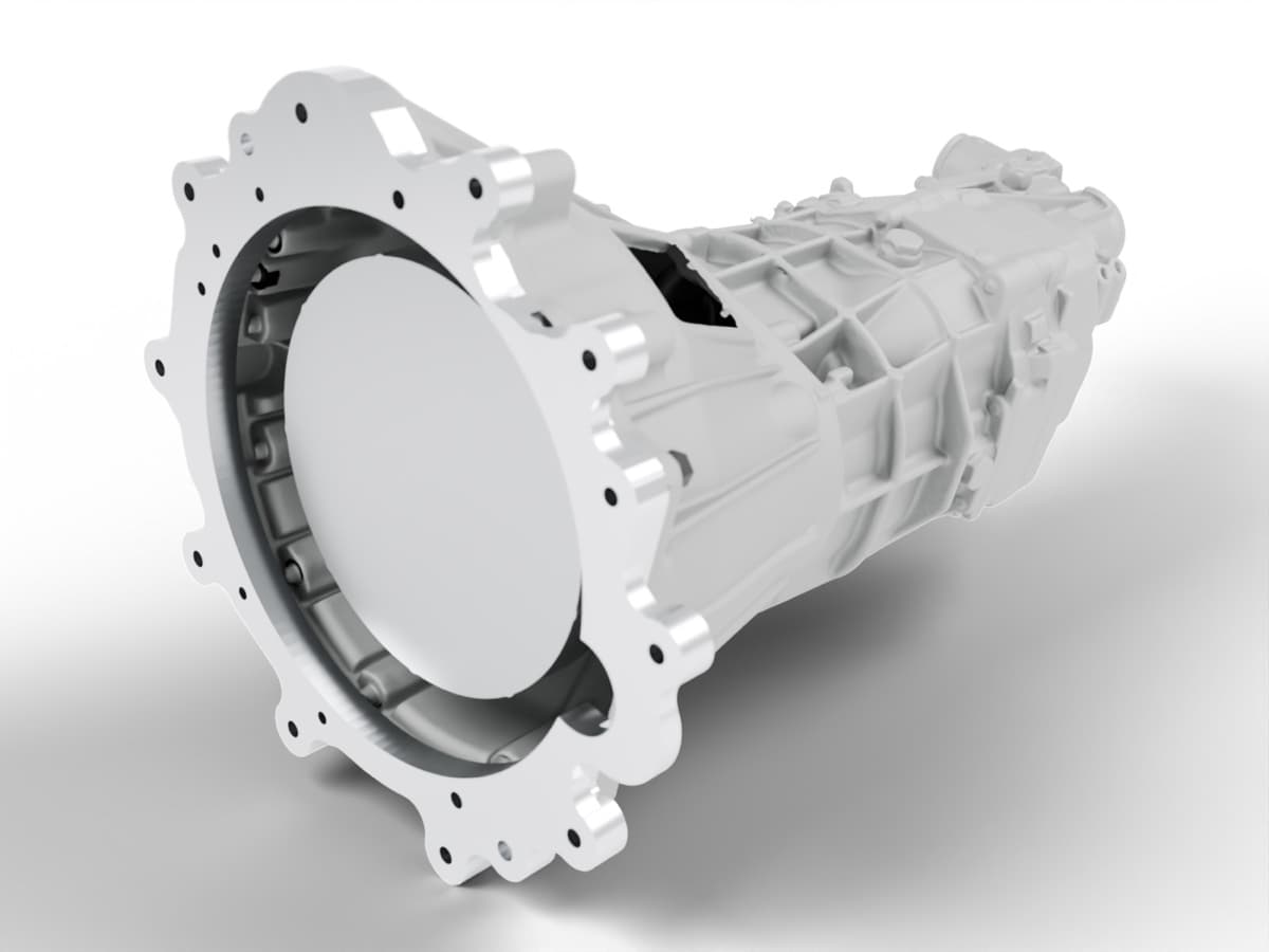
Scan
gearbox case and bellhousing
From the mesh we measure the flange plane, the bellhousing axis and 8 bolt holes.
- 02
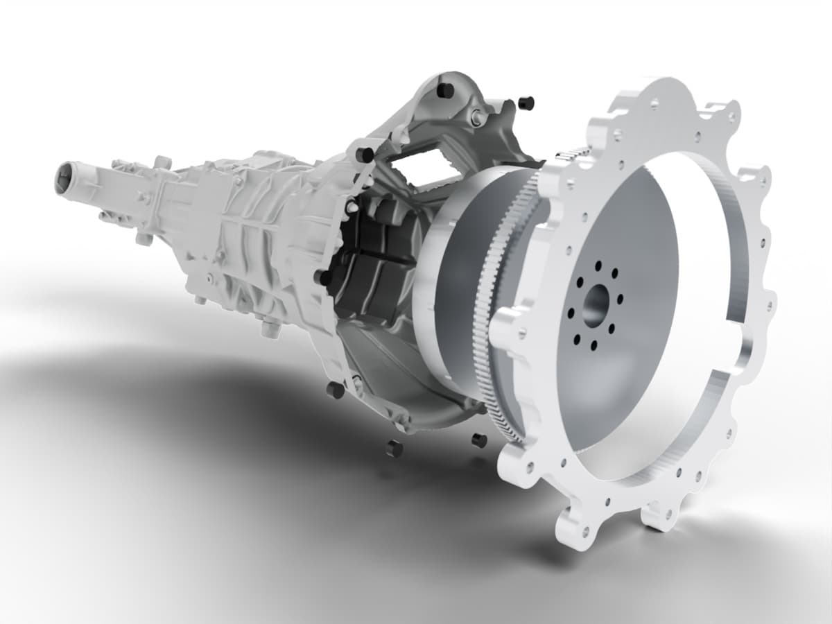
CAD model
two-level plate
A contact band following the bellhousing, counterbored towers, ribs and pockets.
- 03
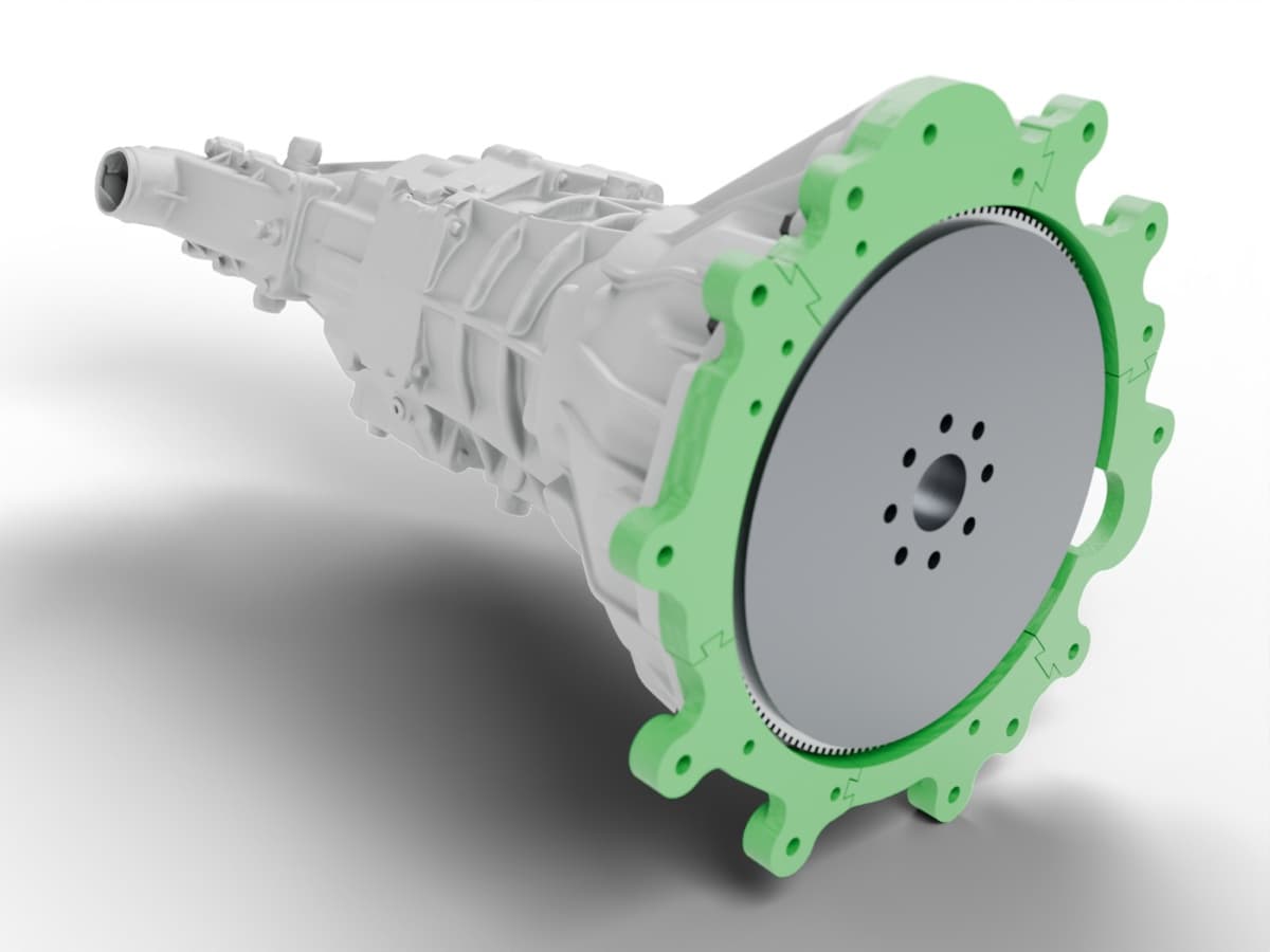
PLA trial fit
FDM, 6 glued segments
The plate is too big for a printer, so we print it in pieces and glue them. For the trial fit only: holes, dowels, flywheel, starter.
- 04
CNC aluminium
EN AW-6082 T6 at a partner shop
The same STEP file goes to the mill only once the plastic fits.

Problem
An engine swap almost always comes down to an adapter plate. The engine side carries the block's bolt and dowel pattern, the gearbox side the bellhousing pattern, and in between the crankshaft axis has to line up with the gearbox input shaft. Add a large opening for the flywheel and ring gear, and room for the starter pinion. There is rarely any documentation for the bellhousing, and castings differ between model years. Machining a 440 mm plate from solid aluminium is the most expensive step and takes days. If one hole ends up 2 mm off, the plate has to be ordered again.
Outcome
The package from this study: bellhousing flange measurements from the scan, a parametric plate model (changing a bolt pattern regenerates the whole plate), a template and a trial-fit part ready to print, a STEP file and drawing IE-030 for the machinist. The same method works wherever a metal part has to fit something you cannot try on in CAD: engine plates, flanges, brackets, bearing housings, pump adapters. 3D printing does not replace the aluminium here. It does something more useful: it makes sure the aluminium is machined once.
- 01Scan. We scan the whole gearbox, the bellhousing inside and out. We do not copy the scan mesh 1:1, we measure it: cross-sections give the bellhousing bore (about ⌀330) and its axis, a depth map gives the 8 bolt holes (7 on an R171 circle, one by the starter) and their sizes, and the edge of the scan gives the mating plane, because the gearbox stood on its bellhousing and the face itself is not visible. Critical dimensions get checked with calipers.
- 02CAD model. A two-level plate, like proper adapters: a 12 mm ledge and a 20 mm bellhousing contact band that follows the flange outline from the scan exactly. On the bellhousing side 8 M10 and M12 threads (sizes from the scan), on the block side 10 M10 bolts in counterbored towers so the heads hide under the bellhousing. Plus ribs, lightening pockets, two H7 dowels on each side, a ⌀314 opening for the flywheel and a cut-out for the starter pinion.
- 03PLA template. The plate is 440 mm across, which fits no common printer bed. We split the model into 6 segments with dovetail joints, each under 21 cm, print them in FDM on an ordinary printer and glue them together. The first print is a thin 3 mm template: just the outline and the holes of both patterns. We hold it against the bellhousing, then against the block. It shows straight away whether the dowels go in, whether the bolts find their threads and whether the starter cut-out sits where the pinion is. If not, the fix in the model takes minutes, not a new plate.
- 04Full-geometry trial fit. The second print, also glued from 6 segments, has everything the aluminium will have: the ledge, the towers, the pockets. It does not need to look good or be strong, only to check the dimensions, so it is the cheapest possible FDM print in PLA. We bolt the engine to the gearbox with it and check shaft alignment, flywheel and ring gear clearance, starter engagement, spanner access to every bolt and how the input shaft sits in the crankshaft spigot bearing. This is where the mistakes CAD cannot show turn up: a cable, a bracket, a previous mechanic's weld.
- 05CNC at a partner shop. Only once the plastic fits do the same STEP file and drawing IE-030 go out for machining from EN AW-6082 T6 plate. Tight tolerances only where they matter: H7 dowels, hole positions relative to the dowels, flatness. Everything else to ISO 2768-mK, because there is no point paying for precision nobody will use.
- 06Assembly. The aluminium plate goes where the plastic one was, on the same bolts. It fits the first time, because the print has already asked every question.
Specifications
IE-030- Status
- Process study
- Joins
- Toyota 2JZ / 6-speed manual gearbox
- Gearbox side
- From a 3D scan: 8 holes, outline, plane
- Size
- 441 x 443 x 20 mm, 2.2 kg
- Prototypes
- FDM in PLA, 6 glued segments
- Production
- EN AW-6082 T6, CNC machined