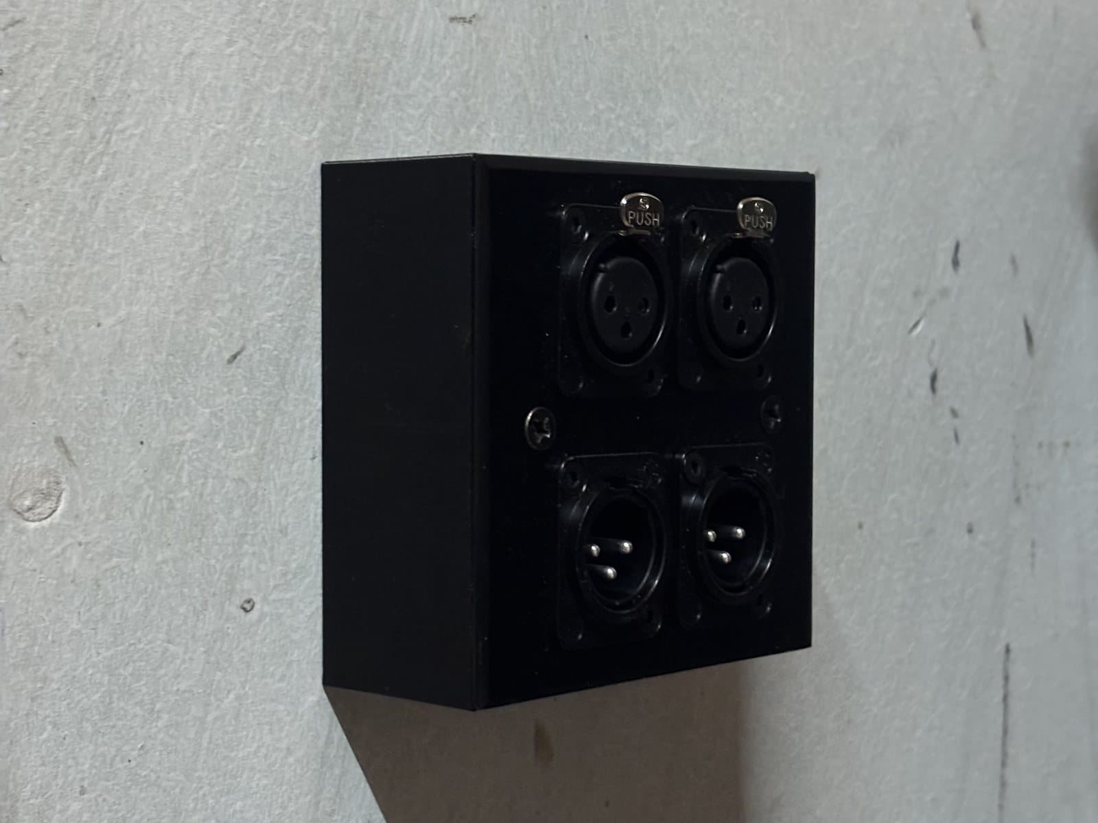
A surface-mount wall box for a 4x XLR plate in a recording studio
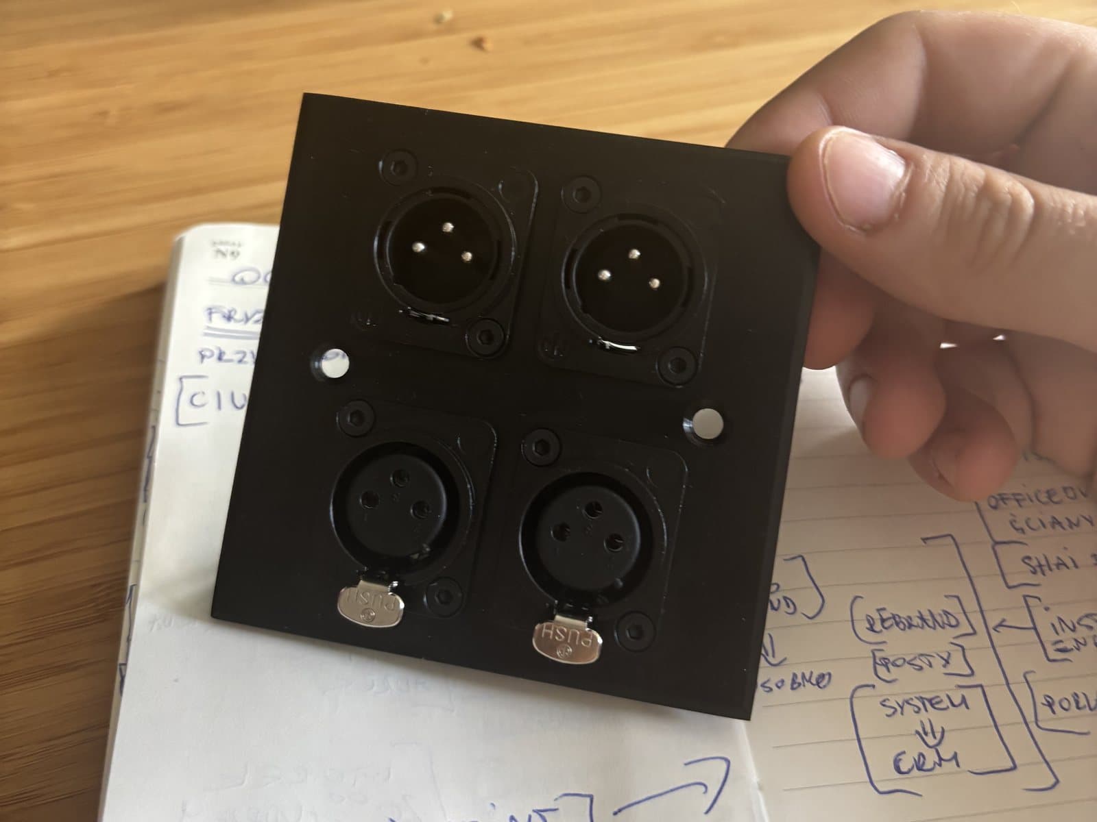
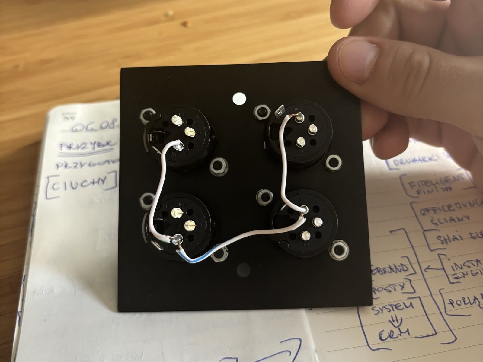
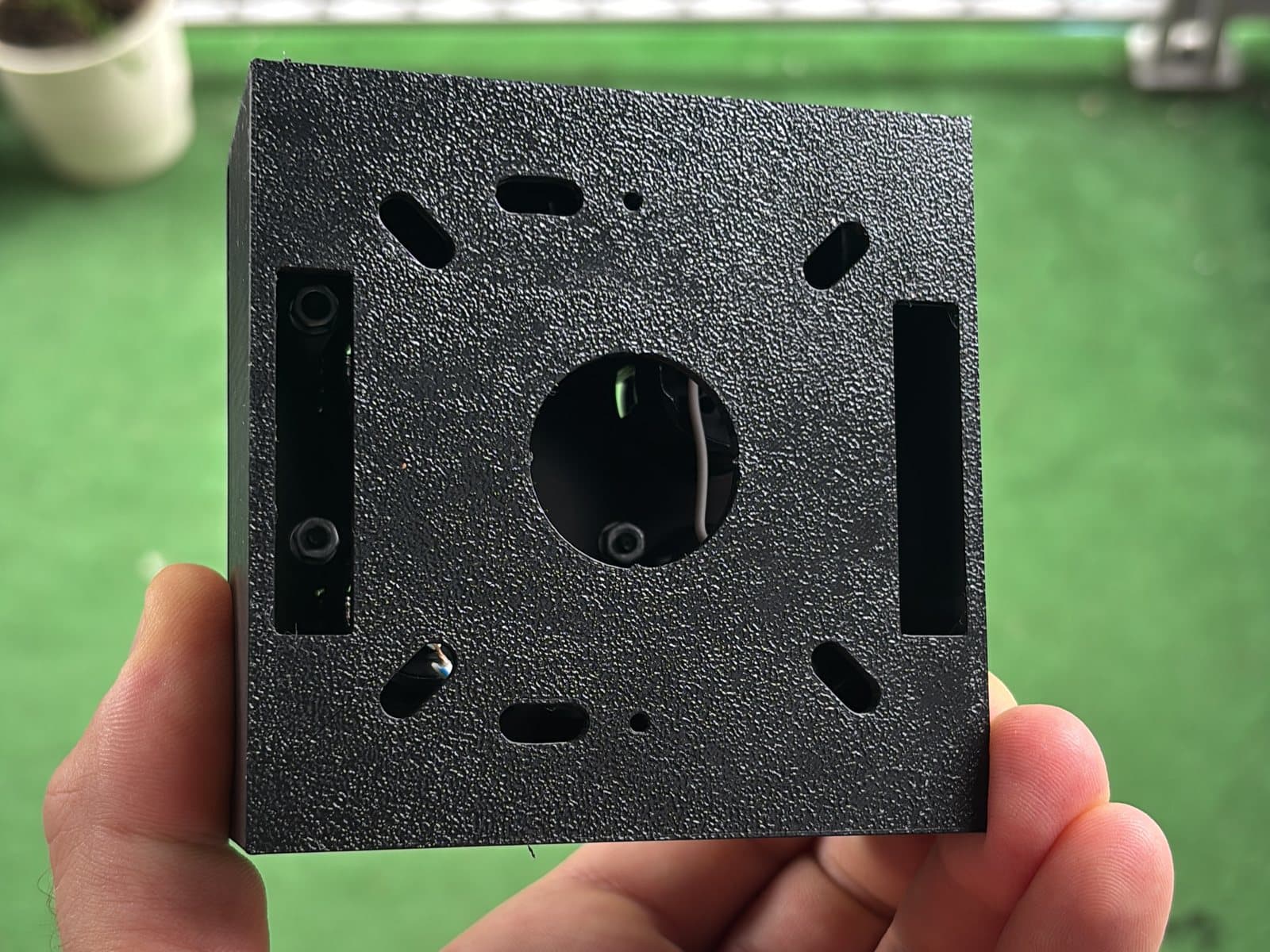
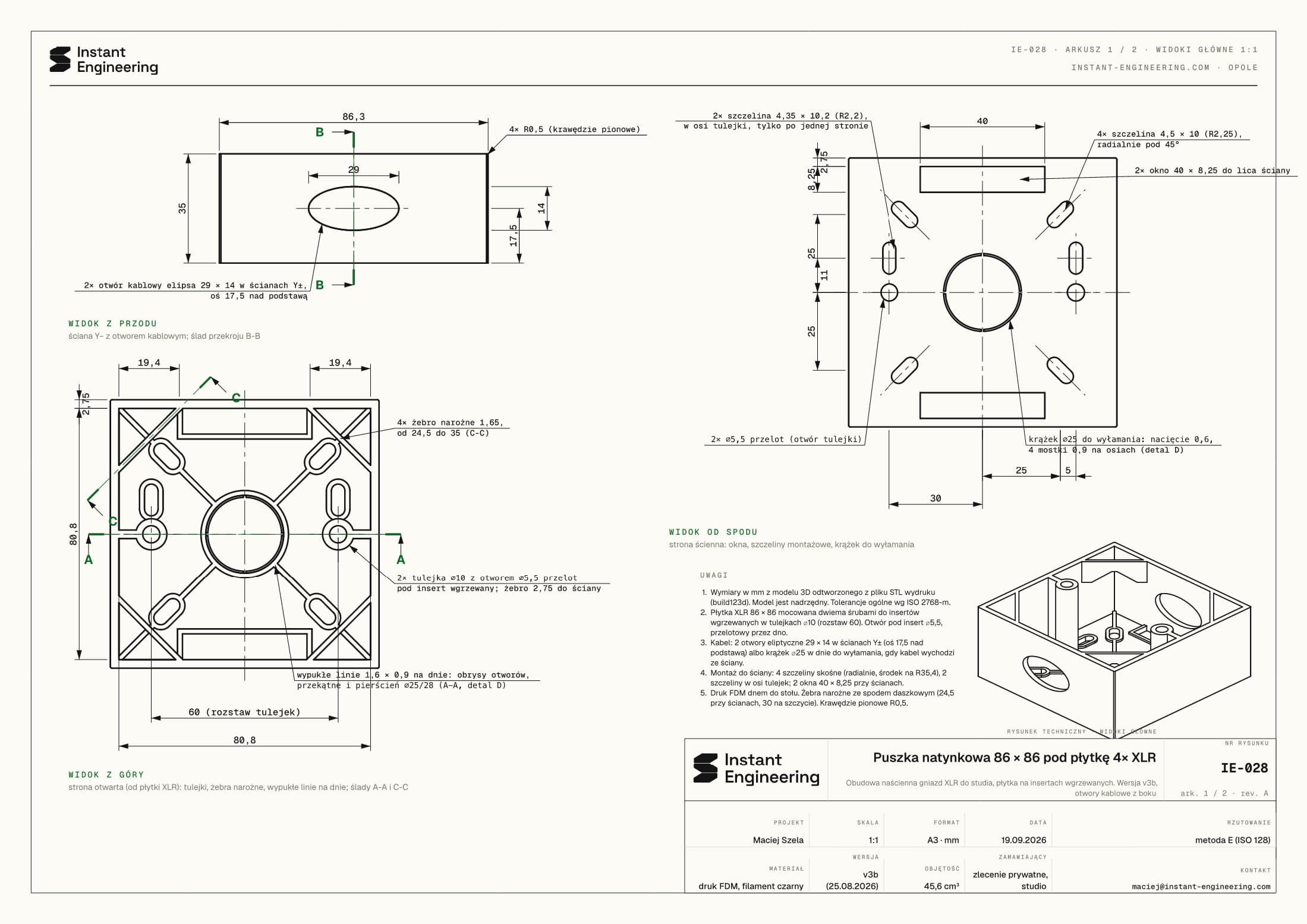
The studio had a ready, wired 86 x 86 mm plate with four XLR connectors but no wall box for it. We designed and printed an 86 x 86 x 35 mm surface-mount box for that plate: two bosses with heat-set inserts for the screws, side cable openings, a knock-out disc in the base and mounting slots. Four versions in four days; the box is on the wall.
Problem
The 4x XLR plate has two screw holes 60 mm apart and, at the back, plugs and wiring that need depth. The box had to hold the plate firmly and repeatedly (a screw into bare plastic is a one-time affair), hang on the wall and take a cable run along the wall or coming out of it. Matte black, so it does not stand out from the plate.
Outcome
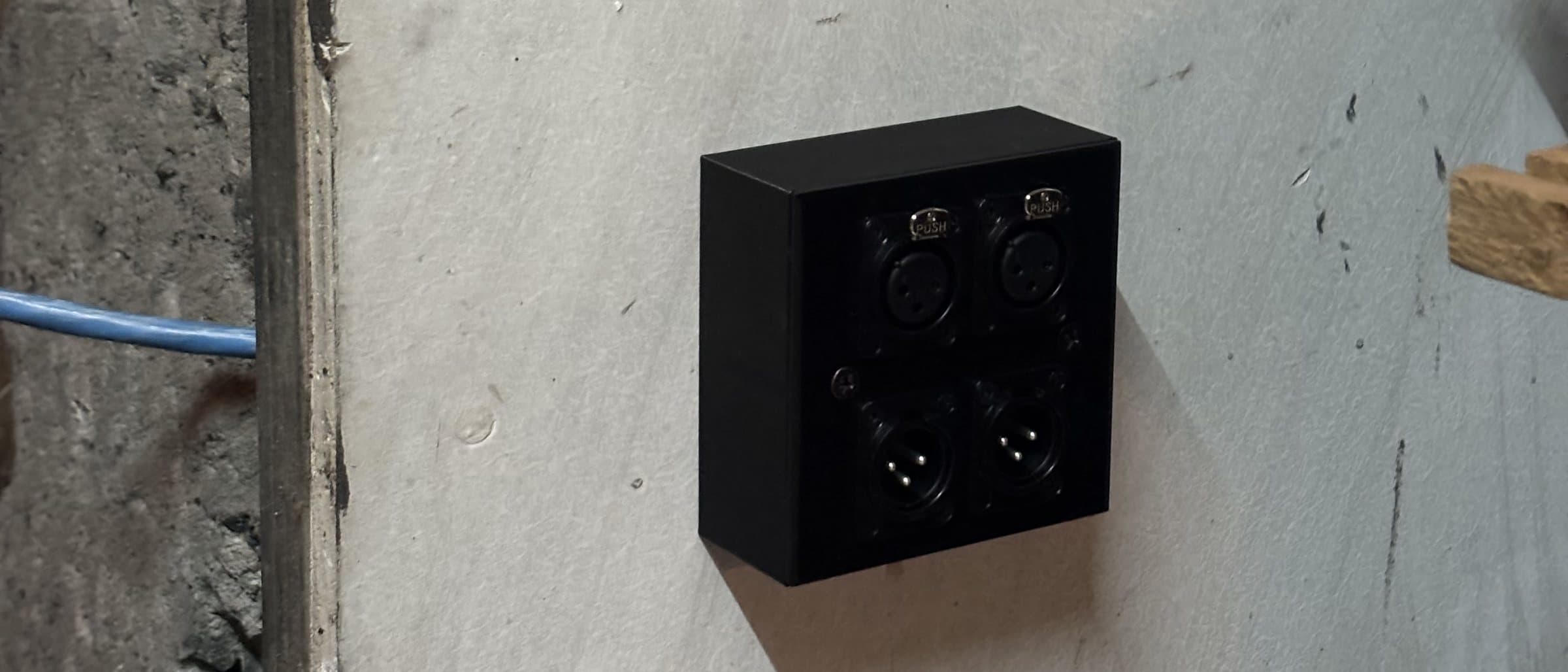
The box hangs in the studio with the 4x XLR plate and looks like part of it, not an add-on. The screws go into brass, so the plate can come off as often as needed. We keep the files and the drawing: another box, a different depth or spacing is a quick parameter change.
- 01Measuring the plate and connectors: 86 x 86 mm, 60 mm screw spacing, depth for the plugs. Hence a box of 86 x 86 x 35 mm with 2.75 mm walls.
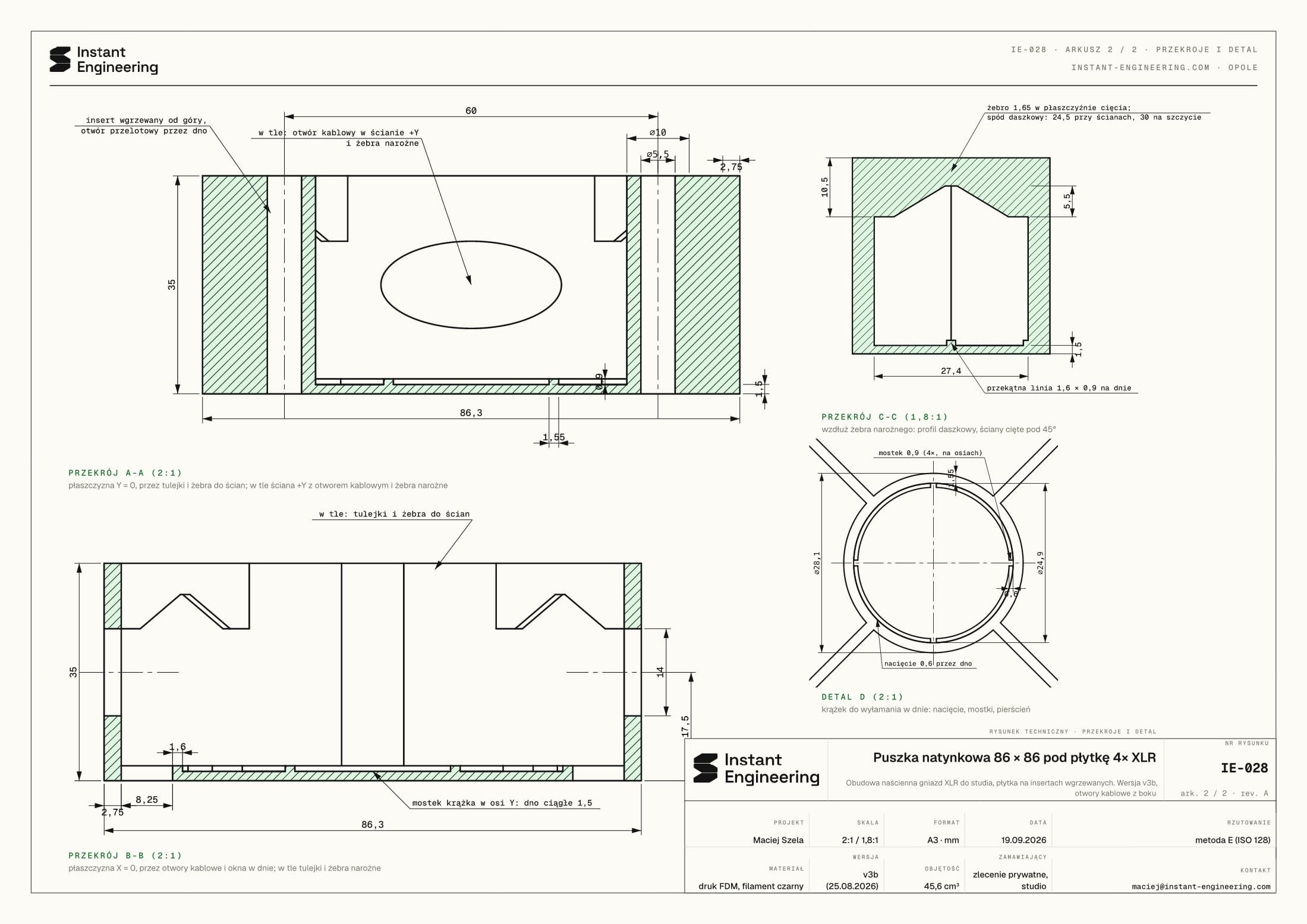
- 02Model in Shapr3D: two ⌀10 bosses with ⌀5.5 holes for brass heat-set inserts, ribs tying the bosses to the walls, corner ribs under the plate. In the base: mounting slots for screws, cable windows and a ⌀25 knock-out disc.
- 03Four versions in four days (v1 to v3b). The last one added 29 x 14 mm elliptical cable openings in two walls so the cable can enter along the wall, not only out of it.
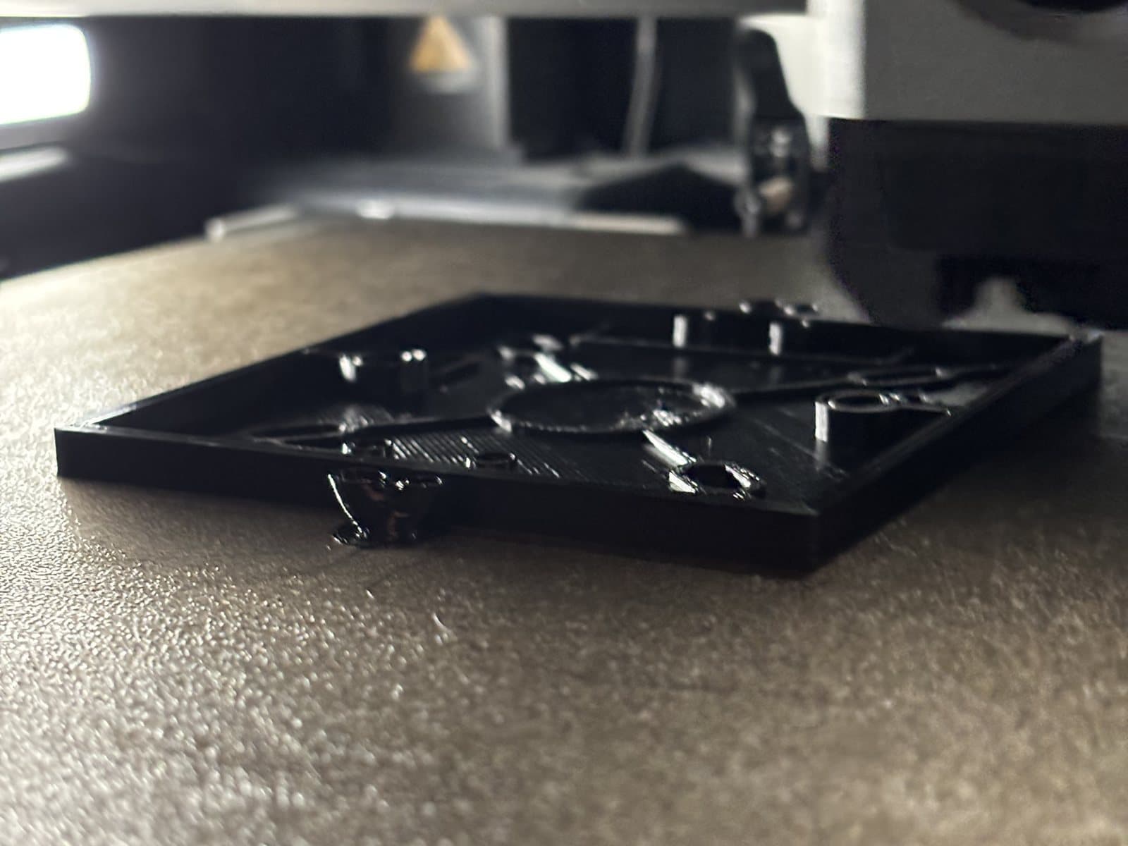
- 04FDM print in black, base down on the bed. Inserts pressed in with a soldering press, straight and to depth, so the plate screws bite into metal.
- 05Installed in the studio: box on the wall, cable in from the side, plate on two screws. Later, technical drawing IE-028 from a model rebuilt from the print file.
Specifications
IE-028- Client
- Recording studio, private commission
- Part
- Surface-mount box 86 x 86 x 35 mm
- Plate mounting
- 2x heat-set insert, 60 mm spacing
- Cable
- 2 openings 29 x 14 mm + ⌀25 knock-out
- Material
- FDM, black
- Iterations
- 4 versions in 4 days